
What Is Ladder Logic in PLC Programming?
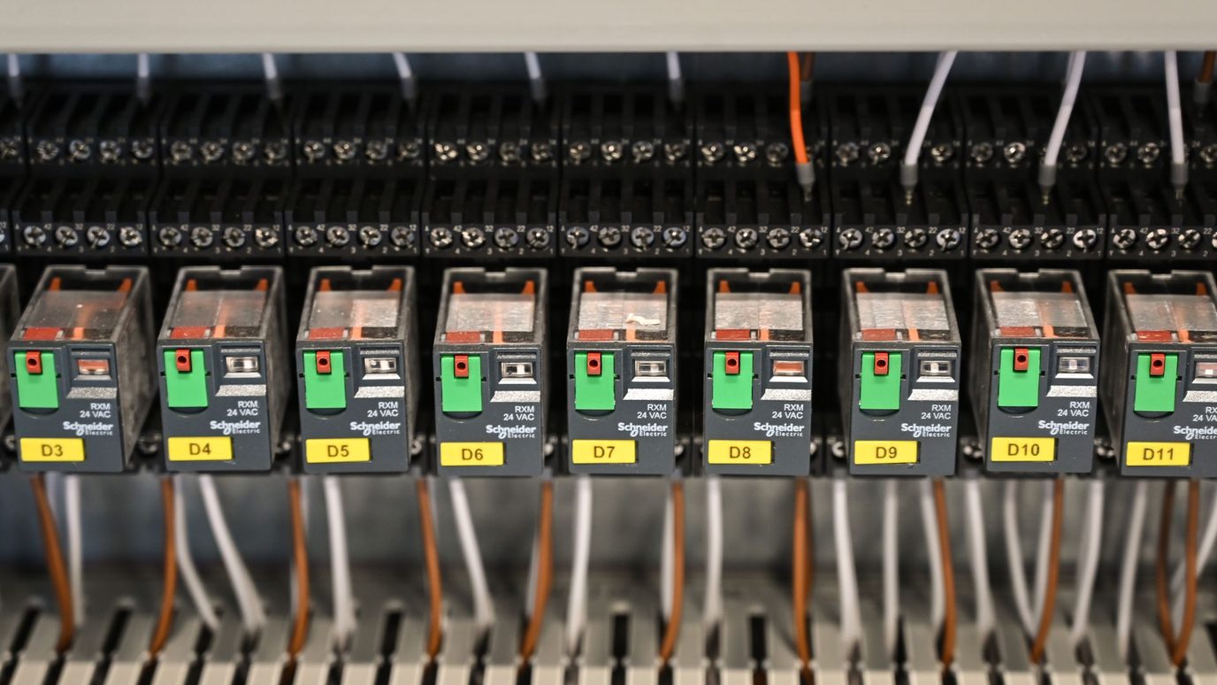
Ladder logic started as a way to document relay racks. Each device was drawn as a symbol, with lines showing how the devices connected. When controllers replaced the relays, the drawing became the program. It kept the look: two vertical rails with horizontal rungs between them, like a ladder.
It stuck for a practical reason. Factory engineers and technicians could write controller programs without first learning a general-purpose language like FORTRAN, and maintenance staff could read the result because it resembled the relay panels they already knew. Ladder logic still runs everything from single machines to very large automation systems.
If the controller itself is new to you, start with our PLC programming for beginners guide, then come back for the rungs.
How Do You Read a Ladder Logic Rung?
Read a rung left to right. The left rail acts as the power source. Contacts on the rung are conditions, and the coil on the right is the output. If a continuous path of true contacts connects the left rail to the coil, the coil turns on. If every path has a false link, it stays off.
- Contacts in series work as AND. Every one of them must be true.
- Contacts in parallel work as OR. Either path can carry the rung.
- A coil switches an output. That can be a physical output like a motor starter, or an internal memory bit that other rungs examine.
The controller does not evaluate every rung at once. It repeats a scan: read the inputs, work through the rungs from top to bottom, then update the outputs. The scan runs many times per second, so the machine appears to react instantly. Because rungs run in order, where you place one can change what the next one sees.
Ladder Logic Symbols and Instruction Names
The same contacts and coil go by different names depending on the software. Siemens calls the contacts NO and NC. Allen-Bradley, the Rockwell Automation brand, calls them XIC and XIO, and calls the coil OTE.
| Symbol | Common Name | Allen-Bradley | True When |
|---|---|---|---|
| Normally open contact | NO contact | XIC (Examine If Closed) | Its bit is on (1) |
| Normally closed contact | NC contact | XIO (Examine If Open) | Its bit is off (0) |
| Output coil | Coil | OTE (Output Energize) | The rung is true |
| On-delay timer | On-delay timer | TON | The preset time has elapsed |
XIC trips up beginners. "Examine if closed" sounds like a closed contact, but it is drawn as the normally open symbol, and it is true when its bit is on. XIO is the reverse. Both examine a bit in memory, not the physical contact in the field.
Ladder Logic Example: A Motor Start/Stop Circuit
This rung turns on a Line_Run output from a green Start button and a red Stop button. On a real machine, Line_Run would drive a motor starter. Most PLC courses teach it first because four instructions cover an input, an output, and memory.
Start_PB and the Line_Run contact sit in parallel, so either one can pass power. Stop_PB sits in series after them, so it can cut the rung whichever path is carrying it. The Line_Run contact is the seal-in. Once the output is on, it feeds its own rung and holds itself on after you let go of Start.
The Stop contact is an XIC on purpose. A Stop button is normally wired closed, so its input reads 1 at rest and drops to 0 when someone presses it or a wire breaks. A broken wire then stops the line instead of leaving it running.
| Moment | Start Input | Stop Input | Line_Run After the Scan |
|---|---|---|---|
| Idle | 0 | 1 | Off |
| Start pressed | 1 | 1 | On |
| Start released | 0 | 1 | On, held by the seal-in |
| Stop pressed | 0 | 0 | Off |
| Stop released | 0 | 1 | Off, because the seal-in was broken |
The last row is the one to remember. With Stop released and nobody touching Start, both paths are false, so the line stays off. This rung is control logic. A machine's emergency stop is usually wired as its own safety circuit and doesn't rely on a rung like this one.
Ladder Logic Example: A Delay Timer (TON)
Timers add time to a rung. Say a belt should start 5 seconds after the line is switched on, so people have time to step clear. Two rungs handle it. The first runs an on-delay timer (TON) while Line_Run is true. The second turns on the belt when the timer is done.
A timer has a preset, which is the time you set, and an accumulated value, which is the time elapsed. While the rung feeding it is true, the accumulated value climbs. When it reaches the preset, the done bit (DN) turns on, and rung 2 passes power to Belt_Motor.
If Line_Run goes false before the 5 seconds are up, an on-delay timer resets and starts from zero next time. Off-delay timers work in reverse. Retentive timers keep their accumulated time until a reset instruction clears it, which makes them a fit for tracking how long a piece of equipment has run between maintenance checks.
Chain the two examples and you have a Start button, a delay, and a belt: a real startup sequence in three rungs.
What Are the PLC Programming Languages?
The IEC 61131-3 standard defines the PLC programming languages. Ladder diagram, function block diagram, and sequential function chart are graphical. Structured text and instruction list are text. The fourth edition, published in May 2025, dropped instruction list, which had been deprecated since the 2013 edition.
| Language | Style | Where It Fits |
|---|---|---|
| Ladder diagram (LD) | Graphical | Machine control and troubleshooting, because it reads like relay wiring |
| Function block diagram (FBD) | Graphical | Connected blocks, popular for process and analog control |
| Structured text (ST) | Text | Math, loops, and complex logic, in a style close to Pascal |
| Sequential function chart (SFC) | Graphical | Machines that run in stages, with steps and transitions |
| Instruction list (IL) | Text | Low-level code, deprecated in 2013 and removed in 2025 |
Older machines still carry instruction list, so you may meet it in a maintenance job. For new work, ladder logic, function block diagram, and structured text are the languages to expect.
Ladder Logic vs Structured Text: The Same Rung Two Ways
Structured text writes the start/stop rung as a single line.
Line_Run := (Start_PB OR Line_Run) AND Stop_PB;Read it the way you read the rung: Start or the output's own state, and Stop. Structured text pulls ahead when the logic is math, loops, or large blocks of data, where a ladder drawing would sprawl across many rungs.
Ladder logic pulls ahead when someone has to watch the program run. A technician can open the rung online, see which contact is false, and find where power stops flowing. That is why troubleshooting on a factory floor leans on ladder logic.
Which PLC Language Should You Learn First?
Learn ladder logic first. It's the quickest to read, and ladder logic edits are part of the daily work for automation technicians and controls engineers, and PLC software is on O*NET's technology list for mechatronics engineers. A practical order:
- Learn basic electricity. Relays, contactors, and normally open versus normally closed devices.
- Build the two rungs above. Use a trainer or simulator until you can predict each scan without looking.
- Add counters and comparisons. They use the same rung pattern as timers.
- Pick up structured text. It is the next language most programmers add.
Employers name the platform, usually Allen-Bradley Studio 5000 or Siemens TIA Portal. The instruction names change between them, but the rung logic carries over. Colleges teach this on real controllers: compare them in our ranking of the best PLC training programs or the best PLC certificate programs. If you'd rather earn while you learn, read about mechatronics apprenticeships.
Common Ladder Logic Mistakes for Beginners
- Putting Stop in the wrong place. Place it in series after the seal-in. Anywhere else, the seal-in can keep feeding the coil while Stop is pressed.
- Mixing up XIC and XIO. Check whether the field device is wired normally open or normally closed first. The instruction examines the input bit, not the label on the button.
- Writing one output in two rungs. The rung scanned last decides the output's state, so the first rung's result gets overwritten.
- Ignoring rung order. The controller evaluates rungs in sequence, so a rung that reads a bit before another rung updates it sees the previous scan's value.
Ladder Logic FAQ
What Is Ladder Logic?
What Is Ladder Programming in a PLC?
What Are the PLC Programming Languages?
Is Ladder Logic Hard to Learn?
What Does XIC Mean in Ladder Logic?
Is Ladder Logic Still Used?
Should You Learn Ladder Logic or Structured Text First?
Sources: IEC 61131-3:2025 (language suite, fourth edition), IEC 61131-3 overview (language list, 2013 deprecation of instruction list), Ladder logic overview (relay origin, scan behavior), RealPars on ladder logic basics (XIC, XIO, OTE naming), and PLC Academy ladder logic examples (seal-in circuit, normally closed stop button, timers).